?Have you noticed how a perfectly machined part can feel like tribute — small, quiet, and unnervingly exact — and then wondered what engineering made that impossible precision possible?

The Hidden Engineering Behind 2026’s Most Precise CNC Spindles
You’re about to wander through the inner life of the spindle, that humming cylinder at the heart of your CNC machine that either makes your parts sing or keeps you awake at night polishing rejects. This is less a manual and more an affectionate, slightly sarcastic tour of what the best spindle engineers in 2026 have been doing to squeeze microns out of steel, ceramic, and a few clever bits of software.
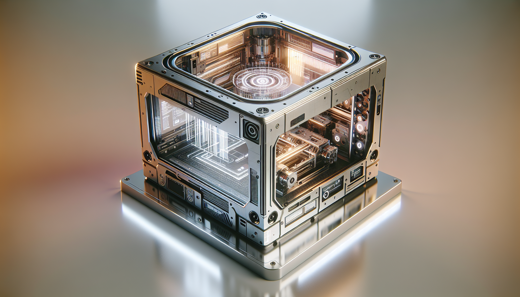
Why the spindle matters — more than you might think
You expect the spindle to spin and hold a tool. You may not expect it to be the single biggest determinant of surface finish, part accuracy, and cycle time. When you tighten your tolerance to the sub-micron realm or ramp spindle speed to chase throughput, everything about the spindle matters: bearings, rotor balance, thermal behavior, the drive electronics, and even the way coolant mist behaves on a moonless night. This section frames why spindle engineering is the quiet hero of modern machining.
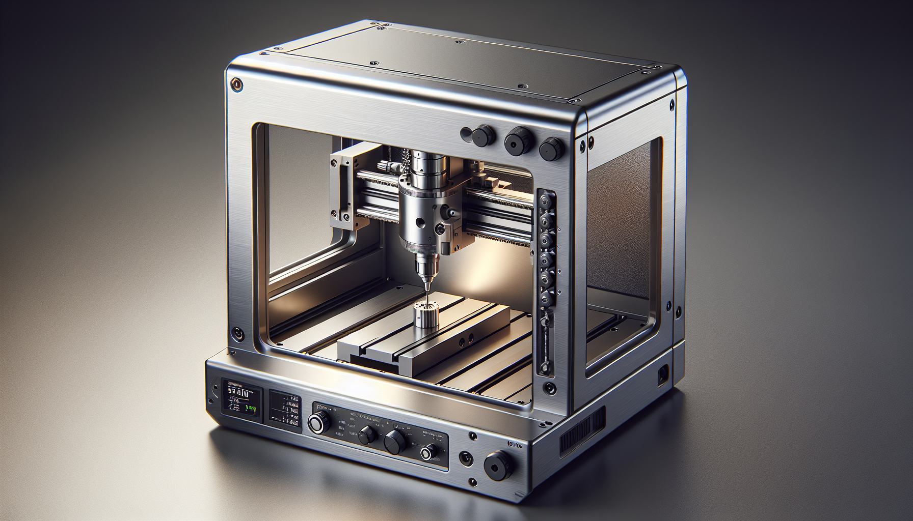
What exactly is a CNC spindle?
You can think of a spindle as three basic things combined into one: rotor, bearings, and drive. It’s the mechanical axis that turns a tool, integrated with cooling, sensors, and the connection to your toolholder. In practice the spindle also carries an identity crisis: part precision instrument, part motor, part pump (if it has a coolant-through tool), and part data node.
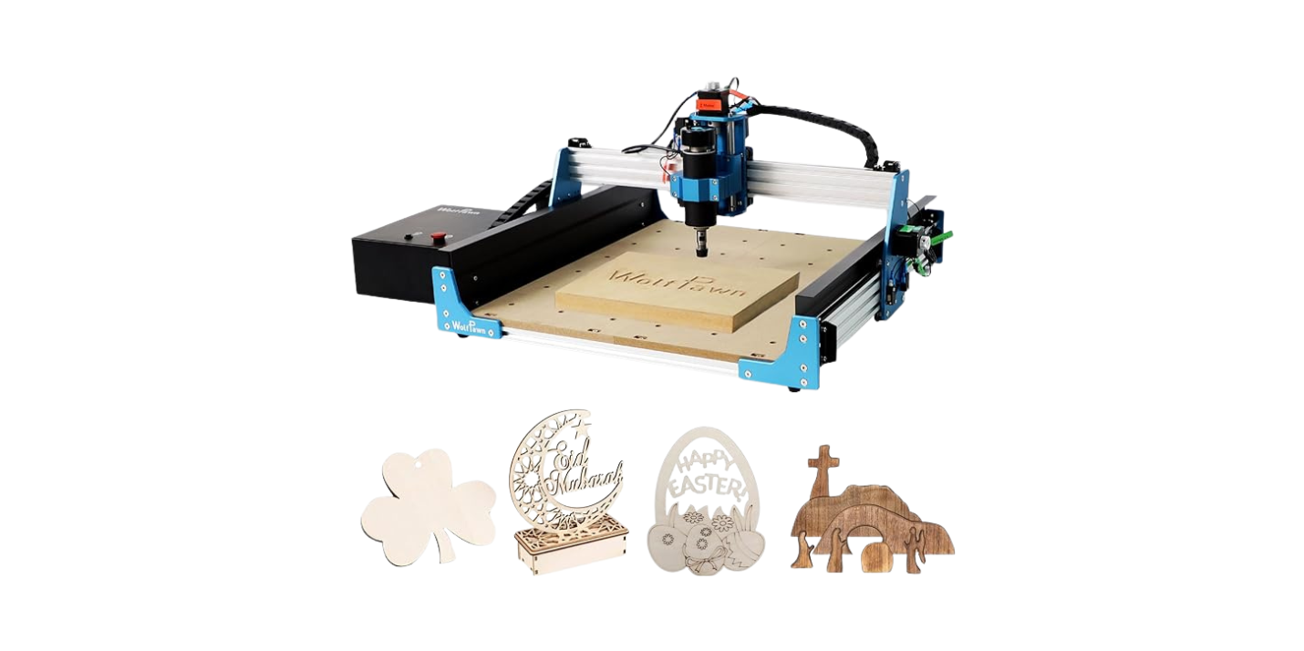
Key spindle types
You’ll run into several architectures in production shops and prototype cells. Each has tradeoffs that influence precision, cost, and maintainability.
| Spindle Type | Typical Use | Pros | Cons |
|---|---|---|---|
| Belt-driven | General machining | Cost-effective, good for moderate torque | Belt stretch at high rpm, lower dynamic stiffness |
| Direct-drive (integral motor) | High-speed milling, precision work | High responsiveness, lower vibration | More complex cooling, higher cost |
| Geared (speed-increasing) | High top-speed applications | Achieves high rpm with lower motor speed | Gear wear, more moving parts |
| Air-bearing | Ultra-precision, metrology | Near-zero friction and contact-free support | Requires clean air supply, expensive, limited load |
| Magnetic-bearing | Ultra-high precision + active control | No contact wear, active vibration suppression | Complex control, cost, sensitivity to EMI |
You’ll pick a type based on speed, torque, stiffness, and the environment you keep your machine in. That pick cascades into bearing choices and control strategies.
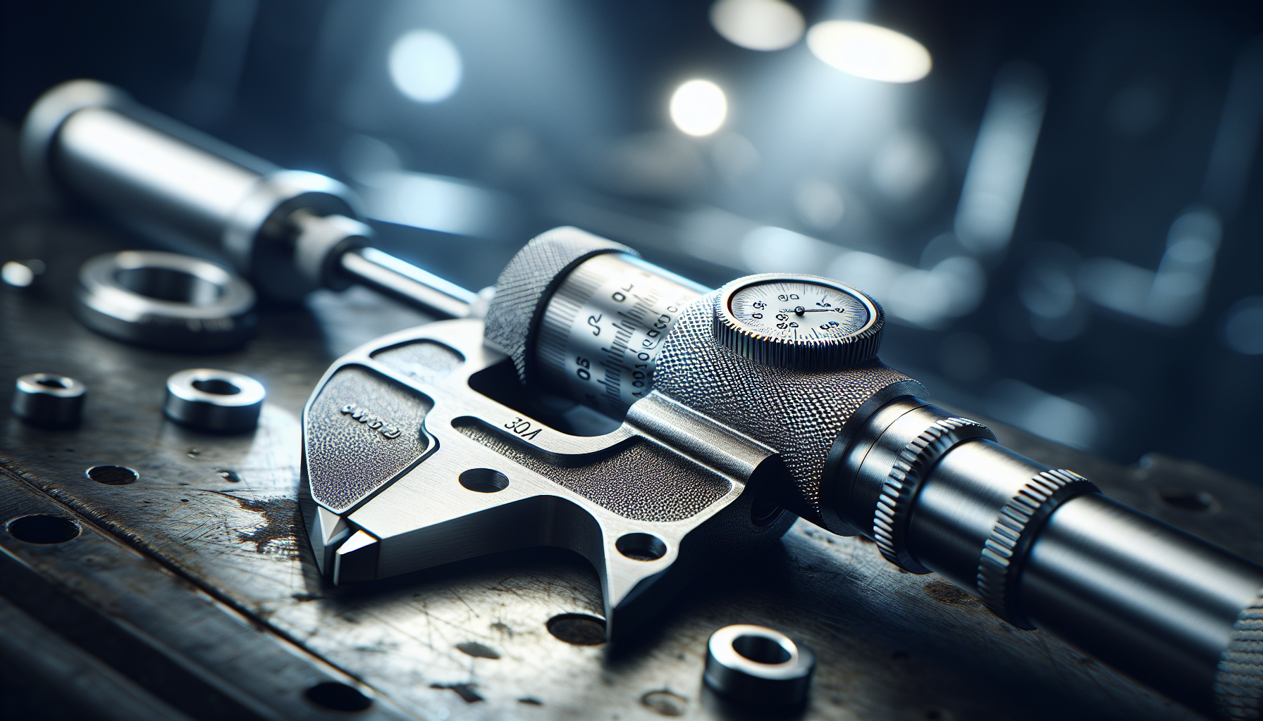
Precision metrics and how they affect your parts
Engineers measure spindles with the kind of grim thoroughness you reserve for tax forms. You need to understand the metrics because they tell you what your spindle will actually do to a machined surface.
- Runout (radial and axial): The eccentricity of the tool tip as the spindle rotates. This is the direct killer of centerline tolerances and concentric features.
- Stiffness/rigidity: How the spindle resists deflection under cutting loads. Lower stiffness = higher deflection = lower dimensional accuracy in deep cuts.
- Thermal growth: Drift caused by temperature gradients. A tenth of a degree can mean microns of growth.
- Vibration (NVH): Resonant peaks and chatter frequencies that spoil surface finish.
- Torque and power curves: How much cutting capacity you have at different RPM.
- Dynamic balance: How well the rotor mass is distributed to minimize forces across the spindle bearings.
Typical precision targets for 2026 high-end spindles
| Metric | Typical value (2026 top-tier) | Why it matters |
|---|---|---|
| Radial runout (at tool nose) |