Have you ever stood in front of a workbench, a 3D printer, or a pile of raw stock and wondered what alchemy transforms those bits and blobs into something that actually works?

The Fabrication Stack: Hardware, Software, Materials, And Skill
This is your map for turning ideas into objects. You’ll read about the four layers that make fabrication possible, how they interact, what mistakes will make you sigh into your tea, and what habits will make you inexplicably smug at a launch party. The stack is straightforward in concept and mischievously complex in practice — like a recipe where every ingredient behaves like it has an opinion.
What the Fabrication Stack Is (and Why You Care)
The fabrication stack is a layered view of the tools and competencies you need to go from concept to finished part. You’ll find that hardware, software, materials, and skill are not separate islands; they are a nervous system where each part transmits signals to the others. Understanding this network helps you design better parts, avoid expensive mistakes, and make decisions that keep timelines manageable.
Why Thinking in Layers Matters
If you ignore a layer, a different one will blame you. When hardware tries to speak software’s language it stutters; when materials throw a tantrum because the design didn’t respect their nature, you spend evenings sanding while trying to remember if “ABS loves acetone” is true or a charming fabrication you read on a forum. Working layer-by-layer reduces those little tragedies.
The Hardware Layer
Hardware is the body of fabrication: machines, tools, fixtures, and the physical environment. It’s the part that bangs, melts, cuts, and glues. You’ll spend a lot of your budget and more of your time here.
Types of Fabrication Hardware
There’s a bewildering parade of machines. Your choice depends on volume, precision, material, and patience.
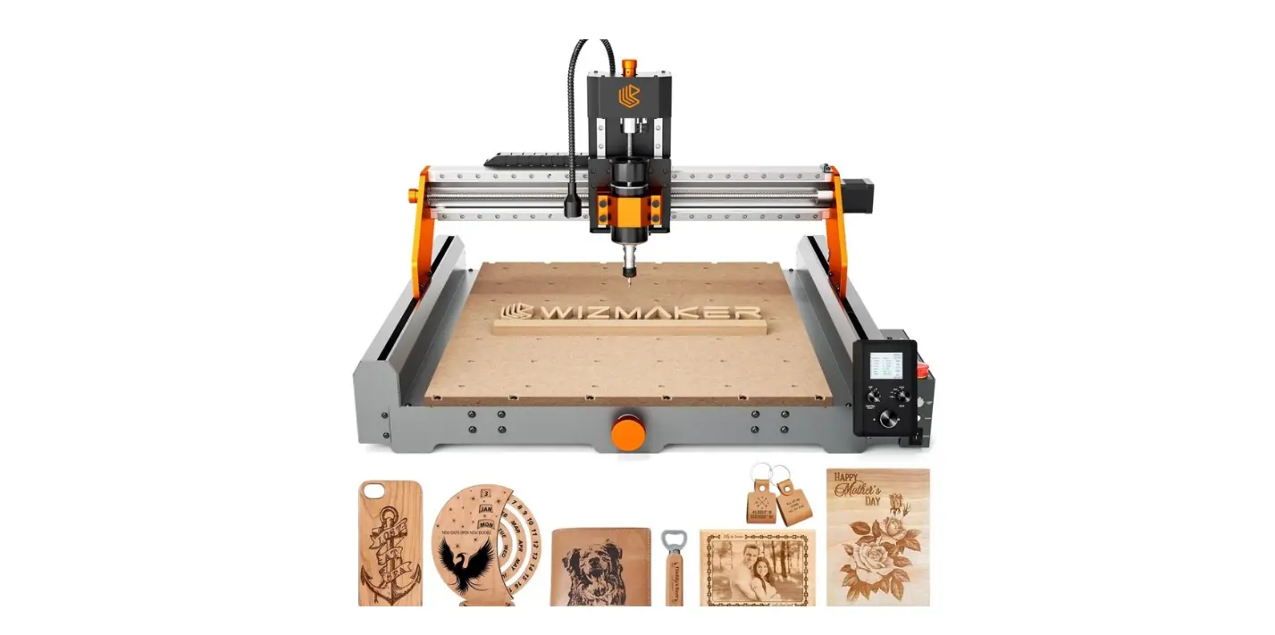
- Subtractive machines: CNC mills, lathes, routers, and waterjets.
- Additive machines: FDM, SLA, SLS, DLP, and metal powder beds.
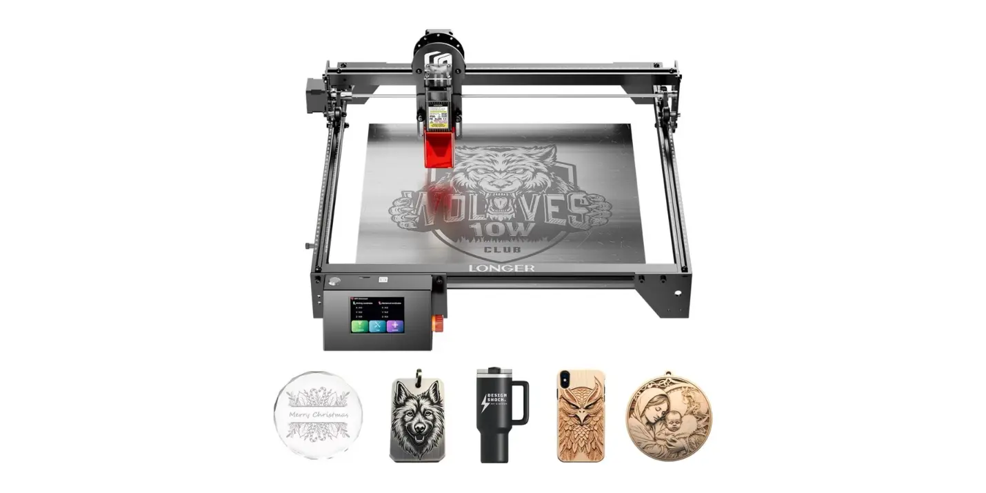
- Thermal and photonic: Laser cutters, plasma cutters.
- Forming and finishing: Press brakes, injection molds, thermoformers, sandblasters.
- Hand and bench tools: Saws, files, hammers, soldering irons, ovens.
- Measurement tools: Calipers, CMMs, profiles, microscopes.
You will get better by starting with the simpler tools and working up; the machines with the fanciest names tend to be the ones that make you realize how wrong your assumptions were.
Choosing Machines: A Practical Comparison
This table helps you match machine types to common needs. It’s not exhaustive, but it keeps you from buying a $15k laser cutter to engrave wooden coasters.
| Machine Type | Best For | Typical Precision | Throughput | Typical Cost Range |
|---|---|---|---|---|
| CNC Mill | Metal parts, precise contours | 0.01–0.1 mm | Moderate | $5k–$250k+ |
| Lathe | Cylindrical parts | 0.01–0.05 mm | Moderate | $2k–$200k+ |
| Laser Cutter | Sheet materials, rapid cutting | 0.1–0.5 mm | High | $1k–$50k |
| FDM 3D Printer | Rapid prototyping, plastics | 0.1–0.5 mm | Low–Moderate | $200–$20k |
| SLA/DLP | High-detail resin parts | 0.02–0.1 mm | Low | $300–$50k |
| SLS/Metal PBF | Functional parts, complex geometry | 0.05–0.2 mm | Low–Moderate | $50k–$1M+ |
| Injection Molding | High-volume thermoplastics | 0.05–0.2 mm | Very High | $5k (molds)–$100k+ (machines) |
Machine Maintenance and Environment
Machines are temperamental pets. They demand calibration, clean power, and a stable temperature. Dust, humidity, and an enthusiastic cat will erode precision faster than you can say “tolerance.” You’ll save time by scheduling checks, maintaining tooling inventories, and documenting maintenance tasks.
The Software Layer
Software is the mind of the stack. It designs, simulates, slices, and instructs hardware. Without software, the hardware is a very expensive paperweight.
Categories of Fabrication Software
You work across several software categories, each with its own learning curve and quirks:
- CAD (Computer-Aided Design): Solid modeling, parametric design (e.g., Fusion 360, SolidWorks, Onshape).
- CAM (Computer-Aided Manufacturing): Toolpaths, feeds, and speeds (e.g., Fusion CAM, Mastercam).
- Slicers: For 3D printing, converting models into layers (e.g., Cura, PrusaSlicer, ChiTuBox).
- Simulation and analysis: FEA, thermal, fluid dynamics (e.g., Abaqus, ANSYS).
- Firmware and machine control: GRBL, Marlin, Smoothieware, proprietary controllers.
- MES/Workflow tools: Job tracking, version control, BOM management.
- CAD libraries, parametric templates, and plugins.
You’ll find that your choice of software shapes design decisions. Parametric CAD makes changes less painful; a poor slicer setting makes you swear in new and inventive ways.
Software-Tool Chain Example
A typical simple chain for making a milled aluminum bracket:
- Sketch and parametric model in CAD.
- Export to CAM and set operations (face, pocket, drill).
- Post-process to generate G-code.
- Run simulations, then dry-run on the machine.
- Machine the part and use inspection software for QC.
Software Selection Table
This table maps needs to software examples and your likely learning curve.
| Need | Software Examples | Purpose | Learning Curve |
|---|---|---|---|
| Parametric design | Fusion 360, Onshape | Reusable, changeable geometry | Moderate |
| Detailed surfacing | Rhino, SolidWorks | Complex freeform surfaces | Moderate–High |
| CAM | Mastercam, Fusion CAM | Toolpaths, machining strategies | Moderate–High |
| 3D printing | Cura, PrusaSlicer | Slicing and printer settings | Low–Moderate |
| Simulation | ANSYS, SimScale | Stress, thermal, fluid analysis | High |
| Machine control | GRBL, Mach3 | Run machine G-code | Low–Moderate |
| Workflow & BOM | Odoo, OpenBOM | Manage parts, materials, costs | Moderate |
The Materials Layer
Materials are the temperament and rules of the object you intend to make. They dictate processes, finishes, tolerances, and, on bad days, your mood.
Material Families and Their Behavior
Understanding families helps you pick a path without weeping into scrap.
- Metals (aluminum, steel, titanium): Strong, machinable, often expensive to prototyping in small shops. Metals require consideration of tool wear, thermal expansion, and finishing.
- Plastics (PLA, ABS, PETG, nylon, PEEK): Lightweight, varied properties. Some print brilliantly, others are hygroscopic and demand drying ovens.
- Composites (carbon fiber, fiberglass): High strength-to-weight, challenging to finish and repair.
- Ceramics and glass: Hard, brittle, often precision-limited; useful for insulation and wear surfaces.
- Elastomers (rubber, silicone): Flexible, forgiving in fit, tricky to machine.
- Textiles and leathers: Behavior depends on weave, finish, and coatings.
You will learn the meaning of words like “creep,” “hygroscopic,” and “anneal” — the material layer is where vocabulary acquires force.
Material Selection Considerations
When choosing a material you should consider:
- Mechanical requirements: strength, stiffness, toughness.
- Environmental conditions: UV, temperature, moisture, chemicals.
- Manufacturing limitations: minimum wall thickness, support needs, tooling, surface finish.
- Cost and supply: lead times and scrap rates.
- Regulatory constraints: biocompatibility, flammability, food safety.
Comparative Table: Quick Material Guide
| Material | Strength | Typical Processes | Pros | Cons |
|---|---|---|---|---|
| Aluminum 6061 | High | CNC, extrusion, sheet forming | Lightweight, machinable | Corrodes without treatment |
| Stainless Steel 316 | Very high | CNC, laser cut, weld | Corrosion resistance | Harder to machine |
| PLA | Low–Moderate | FDM printing | Easy to print | Low temp resistance |
| Nylon | Moderate | FDM, machining, injection molded | Tough, wear-resistant | Absorbs moisture |
| Carbon Fiber Composite | Very high | Layup, CNC, molding | High strength-to-weight | Abrasive to tools |
| Silicone | Low | Casting, molding | Flexible, durable | Hard to bond |
The Skill Layer
Skills are what make you less of a hopeful tinkerer and more of a reliable fabricator. They’re the muscle memory, heuristics, and judgment accrued from mistakes that smelled like burnt filament.
Core Skills You Need
You’ll find these skills repeatedly bring you out of jams:
- CAD modeling and spatial reasoning.
- CAM programming and toolpath optimization.
- Material handling and finishing techniques.
- Machine operation and setup (fixturing, coolant, tooling).
- Metrology and inspection: reading calipers, interpreting a coordinate measuring report.
- Troubleshooting and iteration: diagnosing layer artifacts or chatter.
- Project management: scheduling, cost estimation, inventory control.
- Communication and documentation: writing clean drawings and change logs.
You’ll also learn that patience is a skill with a surprisingly high ROI.
How Skills Map to the Stack
| Skill | Maps To | Why It Matters |
|---|---|---|
| CAD & Design | Software | Reduces iteration, enables DFM |
| CAM & Machining | Software + Hardware | Protects tools, reduces cycle time |
| Material Knowledge | Materials | Prevents wrong-material disasters |
| Metrology | Hardware + Materials | Ensures parts fit and function |
| Troubleshooting | All layers | Shortens problem cycles |
| Documentation | All layers | Preserves institutional memory |
Developing Skills: Pathways and Practices
You learn faster with deliberate practice. Try these methods:
- Build small projects with clear goals (a hinge, a clamp).
- Reverse-engineer objects to understand choices made.
- Join a community space with mentors and accountability.
- Keep a failure log; reading it later is educational and oddly comforting.
- Teach what you know; explaining clarifies your own thinking.
How the Layers Interact
The stack is not linear. A change in materials can require new tools; a software upgrade can reveal tolerances your hardware can’t meet. You will often find negotiation meetings in your head where materials demand changes and hardware sighs.
Design for Manufacturability (DFM)
Making something that’s possible to produce should be your first design constraint — not an afterthought. You design within the compromise space of the stack:
- Limiting undercuts and thin walls for injection molding.
- Choosing fillet radii that your mill can produce.
- Designing features that minimize supports in 3D printing.
You’ll save money and dignity by asking, early and often, if your design respects the chosen manufacturing method.
Feedback Loops and Iteration
Good fabrication has fast feedback loops: sketch -> prototype -> test -> refine. Each iteration should be a lesson extracted, not a ritual of destruction. A habit of small, fast iterations reduces surprise and increases confidence.
Process Workflows: From Idea to Production
A practical workflow keeps chaos at bay. Below is a general process you can adapt.
Example Workflow
- Concept & sketches — quick and messy, then ruthless editing.
- Requirements & constraints — materials, cost, function, environment.
- CAD model — parametric for changeability.
- Simulation — structural, thermal as needed.
- Prototype — choose fastest reasonable method to test the risk.
- Test & refine — functional and fit testing.
- Pilot production — small batch to validate manufacturing.
- Scale & document — prepare for larger runs with tooling and QC.
You’ll occasionally skip a step and regret it; that’s part of the education budget.
Checklists for Each Stage
- Concept: Have you defined the user problem and constraints?
- CAD: Are tolerances and finishes documented?
- CAM: Have toolpaths been simulated and verified in machine coordinates?
- Prototype: Is the prototype representative enough to validate the risk?
- Production: Are tooling, fixturing, and QC plans in place?
Use checklists to keep your optimism from overriding practical concerns.

Case Study 1: A Simple Bracket
Let’s say you need a machined aluminum bracket. Your path will be straightforward and instructive.
- Requirements: Load 200 N, mountable with two M4 screws, tolerance ±0.2 mm.
- CAD: Parametric part so hole spacing can change.
- CAM: Two-sided milling, choose appropriate tool sizes for pockets.
- Hardware: 3-axis CNC mill, proper fixturing and a 3-jaw chuck or vise.
- Materials: 6061 T6 aluminum, matched to expected loads.
- Prototype: Machine one, inspect with calipers and a CMM if available.
- Finish: Deburr, anodize for corrosion resistance.
- Feedback: Test under load and update fillet radii if stress concentrations appear.
You’ll appreciate that this path avoids surprises because every decision was informed by the other layers.
Case Study 2: A 3D-Printed Bracket for Rapid Prototyping
Now imagine the same bracket needs to be iterated three times in a week.
- CAD: Parametric model that you can change from your phone if you must.
- Slicer: Adjust infill and wall thickness to balance strength and speed.
- Printer: FDM in PETG for better toughness than PLA.
- Post-process: Light sanding, solvent smoothing if needed.
- Test: Fit and mechanical testing; iterate.
You’ll trade precision for speed and learn whether the design truly needs metal or is fine in polymer.
Economy and Estimation
Money speaks bluntly. Understanding costs helps you choose the right layer trade-offs.
Common Cost Drivers
- Machine depreciation and hourly rates.
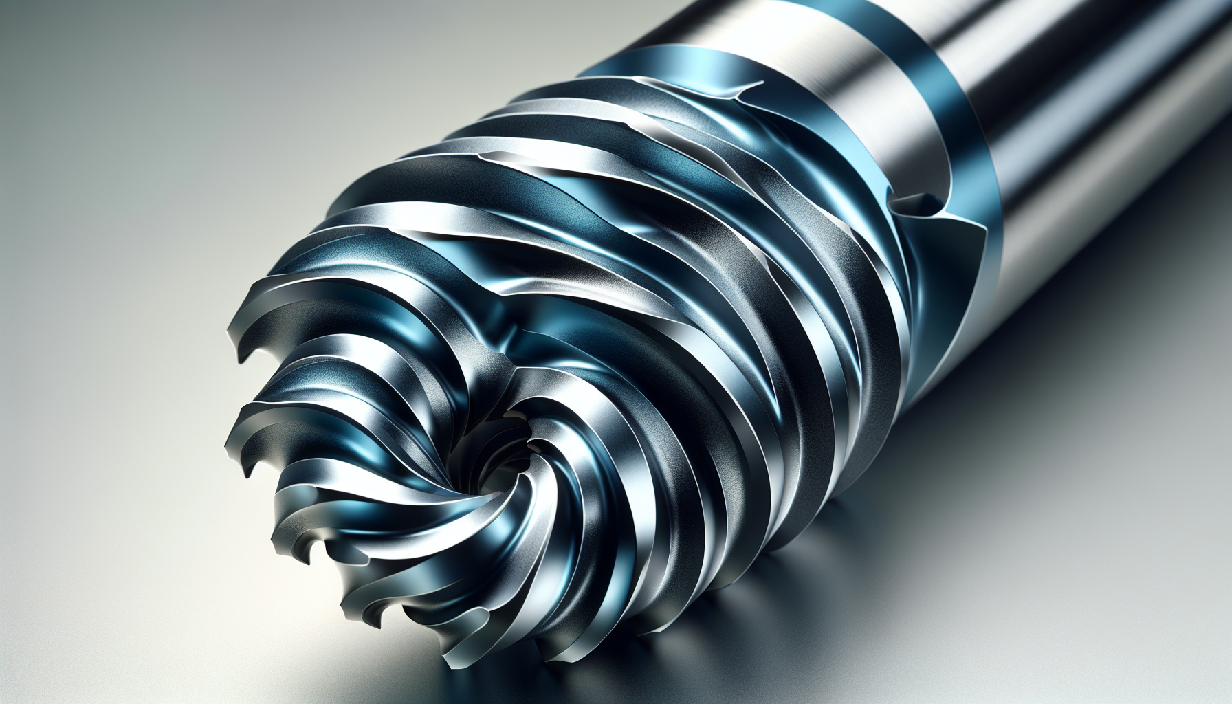
- Tooling costs: end mills, cutters, drill bits.
- Material costs and scrap rates.
- Labor time for setup, fixturing, and finishing.
- Overheads: facility, utilities, inspection.
You’ll be surprised how small inefficiencies multiply. A mis-tuned feeder or a dull tool can double your cycle time.
Example Cost Table (Per-Part Estimate)
| Item | Low-Complexity Bracket | High-Complexity Bracket |
|---|---|---|
| Material | $2 | $8 |
| Machining time | $5 | $25 |
| Tooling (amortized) | $0.50 | $2 |
| Finishing | $1 | $10 |
| Inspection | $0.50 | $5 |
| Total | $9 | $50 |
Numbers vary wildly, but the exercise helps you decide whether to optimize the design or the process.
Quality, Standards, and Documentation
You’ll be accountable to realities like tolerances and standards if you want your parts to assemble right and keep customers.
Tolerances and Fits
- Define tolerances that are meaningful to function, not your ego.
- Use standard fit classes (H7/g6, etc.) for mating parts where possible.
- Document GD&T for critical dimensions.
You’ll learn to prefer explicitness over cleverness on drawings.
Certification and Regulations
If you’re making parts for medical devices, aerospace, or food contact, you’ll navigate regulations, audits, and traceability. That usually means more paperwork and fewer late-night improvisations.
Safety and Sustainability
You’re responsible for other people’s lungs, hands, and reputations. Safety shouldn’t be decorative.
Safety Practices
- Control hazards: guards, lockout-tagout, PPE.
- Ventilation: resin fumes and metal dust are sneaky and patient.
- Training and SOPs: make them short enough to be read on a bad day.
You’ll save money and legal drama by investing in basic protections.
Environmental Considerations
- Material choice affects recycling and end-of-life.
- Minimize scrap by nesting and optimizing layouts.
- Consider energy-efficient processes and local suppliers.
You’ll sleep better knowing your trash isn’t just landfill art.
Community, Ecosystems, and Where to Learn
You don’t need to do this alone. Community and shared knowledge accelerate your learning.
Maker Spaces and Fab Labs
Public labs provide access to machines, experienced users, and a social buffer for embarrassment. You’ll try things there you’d never risk buying.
Online Resources and Communities
Forums, YouTube tutorials, and documentation are great, but beware of myths. Test and verify what you learn. You’ll accumulate a mental library of “what worked” and “what sounded plausible.”
Suppliers and Partners
A good supplier relationship turns material scarcity into a logistical hiccup rather than a production-halting catastrophe. You’ll cherish vendors who answer the phone.
Emerging Trends and What You Should Watch
Technology moves fast, but tastefully: AI-assisted design, modular manufacturing, advanced composites, and localized production are changing choices at all levels of the stack.
AI and Automation
AI can suggest geometries, optimize lattice structures, and tune machine parameters. You’ll still need judgment; AI is an assistant, not a conscience.
Distributed and On-Demand Manufacturing
Short-run, locally produced parts reduce inventory but demand flexible tooling and robust workflows. You’ll move from inventory thinking to capacity thinking.
Materials Innovation
New alloys, bio-based polymers, and printable composites are expanding possibilities. You’ll want to test samples and ignore marketing until you’ve tried the material yourself.
Common Pitfalls and How to Avoid Them
A list is comforting in a low-key, quasi-statutory way. These are habits that will cost you time and dignity.
- Over-specifying tolerances: Only tighten when required.
- Underestimating assembly and fixturing time: Fixtures take effort to design.
- Skipping documentation: You and your successor will thank each other later.
- Not verifying supplier claims: A datasheet is a promise, not a truth.
- Building without tests: Define tests early, not after the failure.
You’ll build a small “disaster fund” of time and money to handle the inevitable surprises.
Tools and Templates to Keep Handy
Practical aids that you will use repeatedly:
- Standard parts library and parametric templates.
- Cut-off and tool life logs.
- Post-process checklists (deburr, wash, inspect).
- BOM templates with supplier info and lead times.
- Digital twin files (CAD + CAM histories).
You’ll sigh with contentment the first time a template saves a Friday.
Final Thoughts: How to Use This Stack
You can treat the fabrication stack like a recipe, a philosophy, or a set of firm rules. The healthiest approach is pragmatic: use the stack to make choices transparent, not to limit creativity. You’ll learn that the best designs are often those that respect constraints as features rather than faults.
- Start with constraints and requirements.
- Choose materials and processes that align with those constraints.
- Use software to make those choices explicit and repeatable.
- Build skills by doing measurable, small projects.
- Keep feedback loops short and documentation honest.
You’ll make fewer mistakes, ship faster, and gain the kind of confidence that lets you stand near a milling machine without flinching. That confidence will serve you well when, inevitably, you decide to prototype something ambitious at 2 a.m.
Resources to Keep Nearby
- CAD tutorials and sample templates (Fusion 360, Onshape).
- Slicer profiles for your printers.
- Tooling catalogs and speed/feed charts.
- Safety data sheets and chemical handling guides.
- Local maker space schedules and introductory classes.
You’ll develop a mental Rolodex of go-to references that saves hours and prevents scrapped parts.
Closing Remark
If you treat fabrication as a stack of interlocking responsibilities — hardware, software, materials, and skill — you’ll stop making the same mistakes and start making usable things. You won’t be immune to frustration, but you will be equipped to handle it with fewer swear words and more elegant solutions. Consider this article a sympathetic companion: it won’t do the cutting, but it will tell you what to forgive yourself for and what to fix before the prototype goes on a plane.